Object Order Empty Space Skipping in OpenGL 4
Haferburg.github.io
When visualizing an iso-surface with ray marching you get this odd performance characteristic that the less you see the more it costs. If the ray hits something, you can stop marching, and compute the pixel color. But if it doesn't hit anything, you will march through the entire volume in vain, performing countless texture accesses for nothing.
So I had this great idea to use the rasterizer to draw an envelope surface first in order to get depth values, which can then be used to determine start and end points for the rays that are much closer to the surface. After implementing it I learned that this idea already existed for a couple of years, and it's called object order empty space skipping.
While this post focuses on the implementation, a more thorough explanation of the technique can be found in the paper "Advanced Illumination Techniques for GPU Volume Raycasting."
How does it work?
The brute force approach to ray marching is to draw a screen-sized quad, and intersect each ray with the volume's bonding box. The obvious improvement is to only draw the front faces of the bounding box, which means the fragment shader will only get called if there actually is an intersection with the bounding box.
Object order empty space skipping takes this idea one step further. You compute a more tightly fitting bounding geometry on a coarse grid (e.g. with blocks of 16x16x16 voxels), and draw this geometry instead of the box.
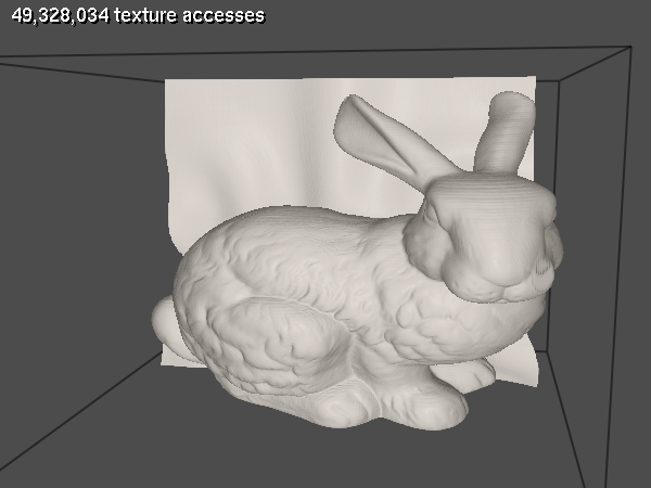
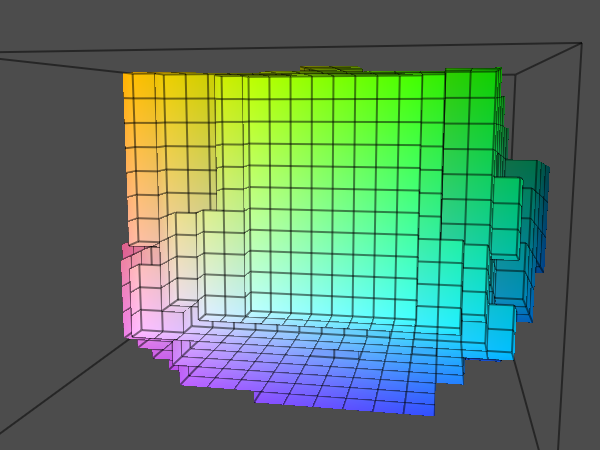
Here's a screenshot of the Stanford bunny data set.
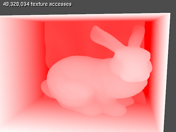
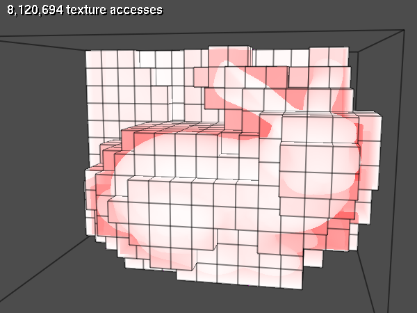
The following image shows the number of texture fetches per fragment:
Here's the geometry that encloses the visible part of the volume for the empty space skipping:
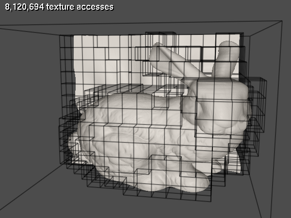
As you can see, the total number of texture fetches dropped significantly even though I used a very coarse grid for the screenshots. Using this geometry, we can determine the improved start and end positions for each ray:
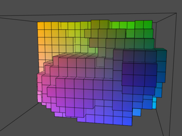
And here is another image visualizing the number of texture fetches per fragment when using the bounding geometry.
Is it worth it?
It largely depends on the volume data. For CT or MRI scans it's probably always faster, because the visible portion of the data is usually very localized. For something like volumetric clouds, the visible data might be scattered all across the volume, so this approach might actually be slower. Note that this optimization is only about skipping rays and finding better start and end positions, so the benefits depend entirely on the locality of the visible data.
Implementation
I use OpenGL 4.3 and C++. The only external dependency is the unofficial OpenGL SDK 0.5.0 (GLM, freeglut, glload). I use a compute shader for computing the grid, and a geometry shader with transform feedback for the bounding geometry. The compatibility profile is used only for text rendering, everything else is core.
Outline
- Given a volume texture with iso values, generate a bounding geometry on a coarse grid. For example, the volume could be 256x256x200, and the grid cells could span 8³ voxels, so the grid dimensions would be 32x32x25.
- First generate another volume texture
gridTex, where each voxel contains the maximum iso value. - Given a threshold iso value, generate the bounding geometry. A grid voxel is considered active if it contains anything visible. For iso-surfaces that means the value is above the threshold. For each pair of neighboring voxels in
gridTex, generate a quad if one is active and the other is inactive.
- First generate another volume texture
- Render the bounding geometry to an offscreen buffer, storing the minimum and maximum depth values for each fragment.
- Render the front faces again.
- Discard if not at the minimum depth value.
- Compute the start and end positions for the ray from the minimum and maximum depth values.
- March the ray as usual.
Computing the grid volume texture
The grid volume texture is generated with a compute shader. For each block, compute the maximum voxel value of all voxels in the block, and also all the voxels adjacent to the block.
Since it is only computed once, it's not that bad to do this on the CPU, but compute shaders are very easy to use and so much faster.
gridTexId = generate3DTexture(GL_TEXTURE1, GL_NEAREST);

glTexStorage3D(GL_TEXTURE_3D, 1, GL_R8, gridDim.x, gridDim.y, gridDim.z);

glBindImageTexture(0, volumeTexId, 0, GL_TRUE, 0, GL_READ_ONLY, GL_R8);
glBindImageTexture(1, gridTexId, 0, GL_TRUE, 0, GL_WRITE_ONLY, GL_R8);

ShaderProgram computeGridProgram;
computeGridProgram.loadShader("grid.comp.glsl");
computeGridProgram.link();

computeGridProgram.use();
computeGridProgram.uniform("volume", 0);
computeGridProgram.uniform("grid", 1);
computeGridProgram.uniform("voxelsPerCell", voxelsPerCell);
computeGridProgram.uniform("volumeDim", volumeDim);

glDispatchCompute(gridDim.x, gridDim.y, gridDim.z);

computeGridProgram.unUse();
And here's the compute shader:
#version 430

layout(local_size_x=1, local_size_y=1, local_size_z=1) in;
layout(r8) readonly uniform image3D volume;
layout(r8) writeonly uniform image3D grid;

uniform ivec3 voxelsPerCell;
uniform ivec3 volumeDim;

void main()
{
  ivec3 ptGridToPos = ivec3(gl_WorkGroupID);
  ivec3 ptVolumeToPos = voxelsPerCell * ptGridToPos;

  ivec3 ptVolumeToMinPos = max(ptVolumeToPos - 1,                 ivec3(0));
  ivec3 ptVolumeToMaxPos = min(ptVolumeToPos + voxelsPerCell + 1, volumeDim);
  int I = ptVolumeToMaxPos.x, J = ptVolumeToMaxPos.y, K = ptVolumeToMaxPos.z;
  float fmax = 0;
  for (int k = ptVolumeToMinPos.z; k < K; k++)
  for (int j = ptVolumeToMinPos.y; j < J; j++)
  for (int i = ptVolumeToMinPos.x; i < I; i++)
    fmax = max(fmax, imageLoad(volume, ivec3(i, j, k)).r);

  imageStore(grid, ptGridToPos, vec4(fmax));
}
Computing the bounding geometry
The bounding geometry is generated by a geometry shader. The input geometry is a number of points, one for each voxel in the grid, and the output is a list of triangle strips.
Storage
The memory requirements for the bounding geometry might become a problem. If the geometry shader emits three floats per vertex position, you'll end up with 6 floats per quad, which is 24 bytes. The worst case is that every other voxel in the grid is active. So for a 64³ grid that's 262k cubes, times 6 sides, times 24 bytes = 37.7 MB. Which seems a little absurd considering that you only need 134 MB for an entire 512³ volume.
However, it's probably a good idea to limit the number of quads of the bounding geometry to something much lower than the worst case. If you get too much overdraw because the bounding geometry becomes too complex, at some point it will get cheaper anyways to draw the entire bounding box instead of the bounding geometry. If all grid cells were active for a n³ grid, the number of quads is 6·n². Now if one grid slice somewhere in the middle were inactive, we would get an additional 2·n² quads. I arbitrarily decided to allow up to 5 such slices, and set the max number of quads to (6 + 5·2)*n². For the example 64³ grid that means 65k quads or 1.5 MB.
In the paper, they store the vertex positions for every grid corner on the GPU, compute indices on the CPU, then upload those to the GPU. However, it's a regular grid, so we don't really need to store the positions, we can easily compute them from the index. So a better way is to emit only indices in the geometry shader, and then compute the grid corner positions in the vertex shaders in the next pass. So instead of three 32 bit floats you only need one 32 bit integer per vertex.
A fast and very easy way to implement that is by using the GL_UNSIGNED_INT_2_10_10_10_REV type for the indices. All we have to do is compute the index in the geometry shader, and we'll get a vec3 in the vertex shaders as usual. 10 bits per coordinate means we can use grid sizes of up to 1024³, and considering the grid cell dimensions are going to be at least 8³, that's probably more than enough for the next couple of years. I've found that there is almost no difference in FPS.
Computation
For using the geometry shader it's not necessary to actually build a big list of points. We can create a list with just one point and use instancing:
GLsizei instanceCount = gridDim.x * gridDim.y * gridDim.z;
glDrawArraysInstanced(GL_POINTS, 0, 1, instanceCount);
In the vertex shader, we can then use the gl_InstanceID to compute the voxel coordinates:
// gl_InstanceID = i + gridDim.x * (j + k * gridDim.y);
int i = gl_InstanceID % gridDim.x;
// jk = j + k * gridDim[1]
int jk = gl_InstanceID / gridDim.x;
int j = jk % gridDim.y;
int k = jk / gridDim.y;
gl_Position = vec4(i, j, k, 1);
In the geometry shader we iterate over each triangle face, and emit a quad if necessary.
void main()
{
  vec3 gridPos = gl_in[0].gl_Position.xyz;

  generateCubeSide(gridPos, vec3(+1,  0,  0), vec3( 0, 0.5, 0.5));
  generateCubeSide(gridPos, vec3(-1,  0,  0), vec3( 0, 0.5, 0.5));
  generateCubeSide(gridPos, vec3( 0, +1,  0), vec3( 0.5, 0, 0.5));
  generateCubeSide(gridPos, vec3( 0, -1,  0), vec3( 0.5, 0, 0.5));
  generateCubeSide(gridPos, vec3( 0,  0, +1), vec3( 0.5, 0.5, 0));
  generateCubeSide(gridPos, vec3( 0,  0, -1), vec3( 0.5, 0.5, 0));
}

float maxIso(in vec3 gridPos)
{
  return texelFetch(gridVolume, ivec3(gridPos), 0).r;
}

void generateCubeSide(in vec3 gridPos, in vec3 normal, in vec3 off0)
{
  float center_intensity = maxIso(gridPos);

  vec3 neighbor_pos = gridPos + normal;
  float neighbor_intensity = maxIso(neighbor_pos);

  // Make sure to only generate one quad, not two.
  if (!(center_intensity >= iso && neighbor_intensity < iso))
    return;

  // Compute the center c of the quad.
  vec3 quadCenter = gridPos + 0.5 * normal;

  vec3 off1 = cross(normal, off0);

  // v0 ----- v2
  //  |     / |
  //  |    /  |
  //  |   c   |
  //  |  /    |
  //  | /     |
  // v1 ----- v3

  emitVertex(quadCenter + off0); // v0
  emitVertex(quadCenter + off1); // v1
  emitVertex(quadCenter - off1); // v2
  emitVertex(quadCenter - off0); // v3

  EndPrimitive();
}

void emitVertex(in vec3 pos)
{
  // pos is a voxel like (23,7,9) offset by e.g. (0.5,0.5,-0.5).
  // Add 0.5 to offset the origin to the cube center.
  // Then convert to ints and pack it into the UNSIGNED_INT_2_10_10_10_REV format.
  ivec3 ijk = ivec3(round(pos + 0.5));
  packedGridToPos = ijk.x + (ijk.y << 10) + (ijk.z << 20)/* + (1 << 30)*/;
  EmitVertex();
}
First pass: Render the depth values
Now we draw the bounding geometry to an offscreen framebuffer object, and store the minimum and maximum depth values in a float texture.
The basic idea is taken from dual depth peeling: Use GL_BLEND with glBlendEquation(GL_MIN) and output both gl_FragCoord.z and -gl_FragCoord.z. What ends up in the buffer is the minimum depth value, and the negated maximum depth value.
When using a 24 bit depth buffer, I would recommend 32 bit floats in the offscreen buffer.
Second pass: Ray-casting
Now the bounding geometry is rendered again. First fetch the depth values from the texture, then perform a depth test.
const float eps = 0.0000001;

void main()
{
  float zwMin, zwMax;
  if (zNearCanIntersectVolume)
    // see below
  else
  {
    vec2 zwMinMax = texelFetch(depthTex, ivec2(gl_FragCoord.xy), 0).rg;
    zwMin = zwMinMax.r;
    if (gl_FragCoord.z > zwMin + eps)
      discard;
    zwMax = -zwMinMax.g;
  }
I wasn't able to persuade freeglut to create a 32 bit depth buffer, which is probably the reason why adding this eps value is necessary. I don't know if this particular value will always work, you'll have to experiment.
Now we can compute the start and end points:
  float zwMax = -zwMinMax.g;

  // All points/vectors in voltex coordinates
  vec3 ptStart = fragmentPos(zwMin);
  vec3 ptEnd = fragmentPos(zwMax);
with
vec3 fragmentPos(in float depthScreen)
{
  vec4 ptVoltexToPos = voltexToViewport * vec4(gl_FragCoord.xy, depthScreen, 1);
  return ptVoltexToPos.xyz / ptVoltexToPos.w;
}
Note that the conversion of viewport coordinates to clip space is encoded in the voltexToViewport matrix. Instead of doing this:
vec4 clipPos;
clipPos.xy = 2.f * (gl_FragCoord.xy - viewport.xy) / viewport.zw - 1.f;
clipPos.z = 2.f * depthScreen - 1.f;
clipPos.w = 1.f;
you can compute a matrix
clipToViewport = glm::translate(-2.0f * vec3(vp.x / vp.z, vp.y / vp.w, 0.f) - 1.f)
  * glm::scale(vec3(2.f / vp.z, 2.f / vp.w, 2.f));
and use that to transform the points:
vec4 clipPos = clipToViewport * vec4(gl_FragCoord.xy, depthScreen, 1);
Of course this only makes sense if you accumulate multiple matrices as in the voltexToViewport matrix, which transforms from viewport coordinate directly to the uvw coordinates of the volume texture.
Dealing with the near plane
Special care needs to be taken if the near plane can intersect the volume. There are two cases. Consider a ray that intersects the bounding geometry four times, at distances s0, e0, s1, and e1, where s0 < e0 < s1 < e1. s0, s1 are the intersections with the front faces, and e0, e1 with the back faces. If the near plane distance n < s0 or e0 < n < s0, we don't need to do anything. We can simply start the ray at the front face as usual. Problematic is the case where s0 < n < e0 or s1 < n < e0. In this case we need to start the ray at the near plane instead.
To detect the second case, we need to find the z value of the closest back face. Note that so far we have accumulated the depth values of the closest front face and the furthest back face. That means we need to add another channel to the offscreen buffer. We can use the gl_FrontFacing variable to detect back faces in the vertex shader:
#version 430

out vec4 outputColor;

uniform bool zNearCanIntersectVolume = false;

void main()
{
  if (zNearCanIntersectVolume)
    outputColor.rgb = vec3(gl_FragCoord.z, -gl_FragCoord.z, gl_FrontFacing ? 1 : gl_FragCoord.z);
  else
    outputColor.rg = vec2(gl_FragCoord.z, -gl_FragCoord.z);
}
If the near plane can intersect front faces, you have to render back faces instead of front faces in the second pass. For early depth testing we can choose to only render the closest or the furthest back face. As long as we find a condition where the fragment shader is executed exactly once per fragment it doesn't really matter.
Note that we didn't check gl_FrontFacing when writing the R component, which means that it contains the closest face (front or back). To detect the second case above, we have to compare the closest back face to the closest face with zwClosestBackFace <= zwMin, and set the starting distance to the near plane.
Here's the omitted portion of the fragment shader for the second pass:
  if (zNearCanIntersectVolume)
  {
    vec3 zwMinMax = texelFetch(depthTex, ivec2(gl_FragCoord.xy), 0).rgb;
    float zwClosestBackFace = zwMinMax.b;
    if (gl_FragCoord.z > zwClosestBackFace + eps)
      discard;
    zwMin = zwMinMax.r;
    if (zwClosestBackFace <= zwMin)
     zwMin = gl_DepthRange.near;
    zwMax = -zwMinMax.g;
  }
Lessons learned
Early depth testing
At first I only computed the maximum z-value in the first pass. In the second pass, I would then render the front faces, and use the z-value of the current fragment as the start point for the ray. However, I would sometimes get horrible frame rates, and in these cases the number of texture accesses would be even higher than when using the entire bounding box instead of the bouding geometry.
What I didn't realize was that depth testing happens after the fragment shader stage. Especially since this fragment shader modifies gl_FragDepth, a fragment can't be discarded by the hardware unless the depth is known. The horrible frame rates occurred when multiple front faces where on top of each other (e.g. looking at a stair at 45 degrees). In this case, the fragment shader would run multiple times per fragment. Note that this problem only occurs because the bounding geometry in general isn't convex.
Regular depth testing can't be used for the second pass. The volume renderer needs to write the depth value of the volume surface, not that of the front faces. But the depth test for the front faces has to be against the other front faces. So the only viable choice is to also write the minimum depth value in the first pass, and manually test against it in the second one.
glBindImageTexture
The layered parameter of glBindImageTexture is kinda weird for 3D textures. Intuitively I set it to GL_FALSE for computing the grid texture, because in my mind the texture is not layered, it's just a 3D texture with one layer. But then the shader wasn't able to modify any voxel uvw with uvw.z > 0. So apparently all 3D textures are considered layered.
Not implemented
The paper I linked above contains a lot more details and techniques, you should definitely check it out.
When using transfer functions with transparency, you need both the maximum and the minimum value of all the voxels covered by the grid cell. A grid cell is active if the transfer function produces a transparency above some threshold for any value between the minimum and the maximum.
If you have additional solid geometry (e.g. an implant or a tool) in the scene, especially when using transfer functions with transparency, you need to render (or blit) the depth values into the max depth buffer after the first pass. Since this affects only the end positions of the rays, you'll have to write to the second component of the offscreen texture (but keep the - sign in mind).
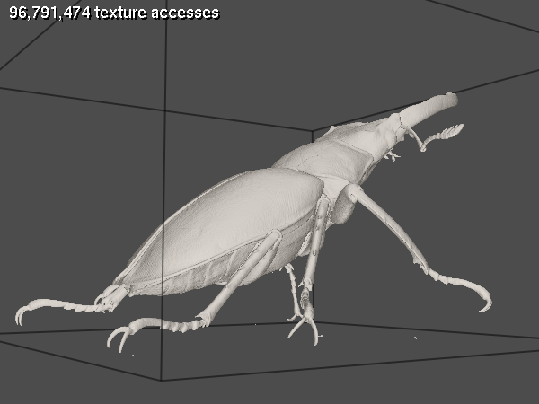
Image order empty space skipping is another technique that complements object order ESS nicely. The idea is to do the ray marching on the grid volume with a bigger step size as soon as you get below the threshold. Here's an example where it might be beneficial. The data set is the stag beetle published by TU Wien.
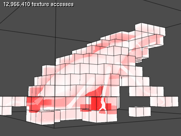
As you can see from the second image, there's a number of expensive fragments where the rays enter the bounding geometry early on, miss one leg, and leave the bounding geometry late after missing another leg. The large space between the legs could be skipped with image order ESS.
Source
Somehow the code kept growing and growing. Mouse/keyboard handling, automatic shader re-loading, volume loading/generation, bunny stripping, debugging, FPS counter, atomic counters, Phong shading, Sobel gradients, pretty wireframe lines... It might have passed the point where one .cpp file is still ok a while ago. But hey, it's free, right? Anyways, here it is. I consider this code to be on the public domain.
I've also included a Win32 executable. Try mouse left, right, wheel, and keys C, B, Q, G, W, A. I've tested it on GTX 400 and 500 cards. It's probably gonna crash if your hardware is not supported. Good luck.
About me
The name's Andreas Haferburg. I've been working as a software developer since 2011, mostly using C++. You can reach me at <first name>.<last name>@gmx.de.